
Filter Press Testing
7.1 Introduction
The goal of filter press pilot testing is to collect the data required to accurately size a full-scale filter press system.
Collected data includes cake solids, cake density, total processing time, processing time each step (filtration, membrane presqueeze, cake wash, membrane squeeze, and cake air blow), slurry feed solids, slurry pH, actual chemical conditioning dosages, and maximum operating pressure for each process step. Other data that is often collected includes filtrate suspended solids, slurry pH, and specific chemical analysis required by the process.
7.1.1 Description of Equipment and Outline of the Test for Pilot Filter Presses
The HPL300, HPL470, and HPL500 pilot filter presses are “sidebar” filter presses each with a manual hydraulic pump. The filter press consists of a frame, hydraulic system, filter plates with filter cloths. The HPL500 can use either 470 mm x 470 mm filter plates (using an adapter plate) or 500 mm x 500 mm filter plates. (The 470 mm x 470 mm plate size is more common in the US while the 500 mm x 500 mm is more common in Europe.) The HPL470 can only use 470 mm x 470 mm plates. The HPL300 uses 300 mm x 300 mm. Other equipment needed for a test includes pumps, and mixing tanks with mixers.
There are two basic filter press configurations: recessed chamber and membrane. Both the HPL470 and HPL500 pilot presses are suitable for all testing for both configurations. A recessed chamber test requires the filter press, feed pump(s), and mixing tank with mixer. A membrane test requires all of the equipment needed for recessed chamber test plus a source of compressed gas for membrane squeeze and the necessary equipment to control the membrane squeeze. The HPL300 is suitable for recessed chamber tests and basic membrane tests without cake washing.
The basic test starts with preparing the slurry or slurry as required for the test and preparing the filter press for the test (installing the correct plates and filter cloth). Once the press and sample are ready the pump is turned on and the press is filled. When the press is filled filtrate will be seen and we start timing and taking filtrate samples. The test is continued until both the low flow and maximum pressure conditions have been reached for filtration. For a recessed chamber test, the test is ended. For a membrane test, it is continued with the optional cake wash, membrane squeeze, and optional air blow down. Once the test is finished the press is opened, the filter cake is removed, and cake samples are taken. During the cake release it is important to note how the cake released and the overall surface condition of the filter cloth. Cake release is normally somewhat better on a larger press but if there is poor release on the test unit the release on the larger unit will be poor.
7.1.2 Filter Cloths
The two criteria for selecting a cloth are the initial quality of the filtrate and cake release. On process applications, it is common to accept somewhat poorer cake release for improved initial filtrate quality. For most waste applications, it is common to accept slightly dirty initial filtrate for improved cake release. It should be noted that both experience and trial and error are used to select cloth. The other major criterion is chemical compatibility of the fabric material with the slurry.
7.1.3 Chemicals and Filter Aids
The chemicals used for chemical conditioning are determined by tests determine proper chemical dosages. Note that for most process applications chemical conditioning is not possible due to contamination of the product.
Ferric chloride solution of known concentration and density, a common, commercially available ferric chloride solution has a concentration of 36% that has a density of 1.378 gm/ml.
Hydrated lime, chemical grade with analysis of 90 – 95 % as Ca(OH)2 or 68 – 72 % available CaO
The hydrated lime should be made up in a 10% w/w slurry to add to the slurry. Normally lime is added to slurry in a 10 – 15% w/w slurry. The density of the 10% slurry is 1.08 gm/ml
Filter aids are usually added as slurries, typically at 10% w/w.
Other inorganic chemicals are added as either solutions or slurries, depending on the chemical.
7.1.4 Test Procedure
7.1.4.1 Slurry and General Preparations
When testing, one should attempt to mimic the expected process conditions as closely as possible, especially with initial pump flow rates. This may be difficult to do because of the pump sizes of the various feed pumps.
If using ferric chloride and lime to slurry add the ferric chloride first and mix well then add the lime and mix well.
If using polymer first make up the polymer solution and allow to age per the manufacturer’s recommendations. For batch addition, add the polymer and gently mix to avoid shearing the floc and occasionally gently mix to prevent excessive settling.
7.1.4.2 Recessed Chamber Test for Pilot Filter Presses
- Install the cloth on the filter plates and put the plates in the filter press frame then close the press and pressurize the hydraulic cylinder to the proper pressure. Note: the procedure for the bench press is in Section 6.4.2
- Calibrate the pumps as required per manufacturer’s instructions.
- Close the press and make sure the closing hydraulic pressure was reached before tightening the locking ring. Close the bottom filtrate valves. Open the top filtrate valves. The air blow inlet valves and wash water inlet valves are closed.
- Prepare the slurry as required with chemical conditioners or body feeds.
- Start the feed pump and any polymer feed pump
- After the press has filled, approximately 2 – 5 minutes, filtrate will be seen coming out the filtrate header. Start timing the run and collecting the filtrate.
- At the designated time intervals note the filtrate volume collected during the time interval and pressure at the end of the interval.
- Depending on the slurry concentration open the bottom filtrate valves from 0 – 6 minutes into the run. Very concentrated slurries (above 50%) should be opened immediately and slurries and slurries with concentrations up to about 8 – 10% should wait until 6 minutes. This is to insure that there is a good cake layer on the entire filter cloth.
- Continue the run until the maximum pressure has been reached and the flow rate has reached 10 – 15 l/m2-hr. At this point, the press is full and the run is over. The total filtration area determines the actual terminal flow rate.
- Turn off the pumps and shut all pump suction valves to prevent siphoning through the pump. Open the slurry drain valve slowly to vent the pressure on the press. Wait until the pressure is 0 psig before opening the press.
- When the pressure is 0 psig and the slurry drain valve still open, open the press, and drop the cake. Each cake is removed and weighed and samples take for cake solids, cake density, cake thickness, and any other analysis required. While removing the cake, observe the cake release and describe as follows:
Table 4. Description of Cake Release from Cloth
| Drop | Cake drops unassisted from the cloth. |
| Excellent | Cake does not stick to the cloth but the dewatered core prevents unassisted release |
| Good | Cake releases with minor assistance |
| Fair | Cake releases with assistance |
| Poor | Cake must be either partially or totally scrapped off the cloth. |
Calculation of Terminal Filtration Rate
Chambers 4
Area per Chamber 0.29 m2
Area of Press 1.16 m2
Terminal Filtration Rate 15 l/m2-hr
Time Interval 5 min
Note plate data is found in Table 12 (for the 470 and 500 mm plates) on page 49, Table 14 on page 55 (for the 300 mm plates), and Table 15 on page 56 (for the bench press).
Terminal Flow Rate in Press:
1.16 m² × 15 l/m²-hr = 17.40 l/hr
Terminal Flow Rate for the Interval:
(17.40 l/hr ÷ 60 min/hr) × 5 min/interval = 1.45 l/interval
Terminal Flow Rate (per min):
17.40 l/hr ÷ 60 min/hr = 0.29 l/min
7.1.4.3 Membrane Test
The membrane test initially follows the Recessed Chamber Test procedure steps 1 – 9 when using the center feed membrane plates. If using the corner feed membrane plates, none of the filtrate valves are closed, and the slurry feed is on the upper right hand corner of the headstand, facing the headstand. Note: the membrane hoses are not attached until later.
- Filtrate is continued until the maximum filtration pressure is reached and the flow rate has reached 30 – 60 l/m2-hr. At this point, the feed pumps are shut off and the isolation valve is closed. The maximum filtration rate is 100 psig without cake washing and 50 psig with cake washing. The calculation of the flow rate is the identical to the calculations shown in Section 6.1.4.2 for the Recessed Chamber Test.
- The membrane hoses are attached to the plates and the plates are inflated at rate of about 15 psig/min.
- If cake washing is to be done the membranes are inflated to pressure of-50 – 60psig, all the filtrate valves except the upper left valve are closed, and the wash water valve is opened. Washing is done until for several minutes with filtrate samples being taken to determine when the cake is properly washed. Note the wash water pressure should be about 70 psig or higher.
- With all the filtrate valves open, continue membrane inflation until the maximum squeeze pressure is reached and maintain the pressure until the filtrate flow has reached 5 – 8 l/m2-hr. The calculations of the flow rate is identical to the calculations shown in Section 6.1.4.2 for the Recessed Chamber Test
- If an air blow is done, all the filtrate valves, except the lower right, are closed and the air inlet valve is opened.
- Once the cycle is over, turn of the gas used to inflate the membranes, vent the membranes, and as described for the Recessed Chamber Test shutting the pump suction valves to prevent siphoning, open the drain and isolation valves and allow the slurry/slurry to drain.
- Once the pressure has been relieved for both the membranes and the slurry inlet, the press is ready to open and for cake release to proceed as described in Step 13 of the Recessed Chamber Test.
7.1.5 Safety Issues
7.1.5.1 Recessed Chamber
- Make sure the filter press hydraulics are pumped to the closing pressure, which is noted by a red needle on the pressure gauge.
- Make sure the locking ring is at least finger tight before feeding the press
- Do not exceed 225 psig on the filter press, if filtering hot liquids (180 – 200°F) the maximum pressure is 100 psig
- When the press is full and the pump is off open the feed vent valve to relieve all pressure on the filter press and feed lines. Leave the valve open until the press is closed for the next run.
- When releasing the hydraulic pressure do not stand along side of the press, there should not be any pressure on the filter press, but if there is any slurry will tend to spew out the side.
7.1.5.2 Membrane
- Observe all the rules for the recessed chamber press.
- Additionally, always make sure that the maximum membrane pressure is 225 psig.
- Also, after inflating the membrane (membrane squeeze will last 15 – 30 min) vent the membranes to atmosphere so there is no pressure on the membranes. Note the gas or water supply should have a shut off or isolation valve before the membrane headers.
- Before opening the press disconnect any hoses connected to the membrane plates, this will insure that the membranes are at atmospheric pressure
- Operating note, leave the membranes disconnected until needed for inflation.
7.2 Special Notes for the HPL470 and HPL500 Filter Presses
7.2.1 Filter Press Description
7.2.1.1 Frame
- Carbon steel frame with sidebars mounted on a skid
- Follower (a.k.a. moveable head) has a moveable extension piece so that it can be moved further out of the way during cake discharge.
- Extension piece has buttons on both ends to ensure proper alignment during closing of the press with the follower and the hydraulic cylinder.
7.2.1.2 Hydraulics – HPL500
- Manual hydraulic hand pump with reservoir and hydraulic cylinder.
- Closing force 400 bar (6000 psig), gauge is in metric units
- Valve on hand pump controls whether hydraulic fluid is going to the cylinder. If closed the fluid is going the cylinder and it is extending. If open the fluid is returned to the reservoir and the cylinder is retracting
- There is a locking ring on the cylinder to mechanically maintain proper press closure. It is tightened done after the press has closed to the full hydraulic pressure. To open increase the hydraulic pressure slightly above the closing pressure and spin the locking ring out of the way.
7.2.1.3 Hydraulics – HPL470
- Manual hydraulic hand pump with reservoir and hydraulic cylinder.
- Closing force 4000 psig
- Valve on hand pump controls whether hydraulic fluid is going to the cylinder. If closed the fluid is going the cylinder and it is extending. If open the fluid is returned to the reservoir and the cylinder is retracting
- There is locking ring on the cylinder to mechanically maintain proper press closure. During a run, one must periodically monitor the hydraulic pressure and maintain the closing pressure.
7.2.1.4 Frontal Piping
- Bolt on headers
- Has center feed four corner filtrate outlets
- For corner feed membrane, ignore center feed, and feed using upper right hand filtrate port (facing the head stand)
7.2.2 Press Operation
7.2.2.1 Recessed Chamber Plates
7.2.2.1.1 Description
- Standard center feed recessed chamber filter plates.
- Cloths are barrel-neck type and are held in place by cloth ties
7.2.2.1.2 Installation
The plates are placed in the press in the proper order. A maximum of 4 chambers (5 plates) can be. In addition, if the necessary additional spacer plates behind the end plate can be installed if the hydraulic cylinder strokes out.
7.2.2.1.3 Operation
- Select the correct cake thickness for the press and install the head, intermediate, and tail plates, alternating the filtrate drainage ports.
- Run filter press in conventional subject to following restrictions:
- Maximum pressure 225 psig
- Low flow flux rate (maximum) 15 l/m2-hr
7.2.2.2 Membrane Plate Stack
7.2.2.2.1 Description – Corner Feed Membranes
- The membrane plate stack consists of a series of membrane plates and “recessed” plates. The plates are alternated: recessed – membrane –recessed – membrane, etc. The membrane plates have a PP welded membrane.
- The slurry is fed into the upper right hand corner of the plates.
- The cloths are individual sheets installed one per chamber side and held in using a locking ring assembly in the corner feed ports.
- An adapter plate is used to “adapt” the 500 mm press porting to 470 mm plate porting of the membrane plates.
7.2.2.2.2 Description – Center Feed Membranes.
- The membrane plate stack is either all membrane plates or alternating as with the corner feed. The selection is based on the initial cake thickness desired. For 40 mm initial cake thickness use all membranes and for 30 mm initial cake thickness use the alternating plate stack.
- The slurry is fed into the center feed port
- The cloths are barrel-neck types except for the tail plate, which is a drape over type. Use cloth ties to hold the cloth in place
- An adapter plate is used to “adapt” the 500 mm press porting to the 470 mm plate porting of the membrane plate
7.2.2.2.3 Installation
- The plates are placed in the press in the proper order. A maximum of 4 chambers (5 plates) can be. In addition, if the necessary additional spacer plates behind the end plate can be installed if the hydraulic cylinder strokes out.
7.2.2.2.4 Operation of Membrane Press
- The press is filled conventionally with the following restrictions
- Feed pressure is 100 psig max.
- Terminal filtration rate is normally about 30 – 60 l/m2-hr.
- The membranes are inflated with the following restrictions:
- Inflation media is compressed gas or water, whichever is more convenient
- Maximum inflation pressure is 225 psig
- The ports on the membrane plates should have quick disconnects on them
- Maximum inflation rate is 15 psig/min
- Note only every other membrane plate needs to be inflated, even if a “full” membrane plate stack is used.
- Full membrane cycle with all steps:
- Fill chamber
- If cake washing, terminal pressure is about 50 psig, otherwise terminal pressure is about 100 psig.
- All filtrate valves are opened when the press is full
- Presqueeze (only done when cake washing)
- Presqueeze pressure about the same as the terminal pressure (~50 psig)
- Wash liquor (usually water) is sent in from lower right to upper left
- Filtrate and feed valves are set so that the wash liquor enters the press from the bottom right and exits the top left
- Wash liquor pressure 60 to 100 psig, determined by experimentation
- Cake washing (optional)
- Final squeeze – all filtrate valves are opened
- Cake air blow (optional) usually done in the opposite direction of the cake wash
Table 5. Valve Setup for HPL470 and HPL500 Filter Press
Valves are identified on the two drawings ” Frontal Piping for HPL470 and HPL500″ and “Membrane Piping for HPL470 and HPL500”.
Figure 3. Frontal Piping for HPL470 and HPL500 Filter Press
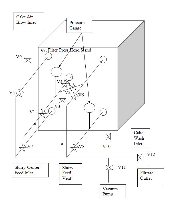
Figure 4. Membrane Piping for HPL470 and HPL500 Filter Press
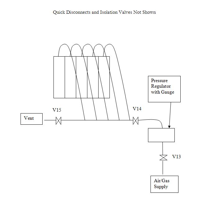
Quick Disconnects and Isolation Valves Not Shown
Table 6. Plate Data for HPL470 and HPL500 Filter Press
7.3 Detailed Operation of the HPL300 Filter Press
7.3.1 Filter Press Description
7.3.1.1 Frame
- Carbon steel frame with sidebars mounted on a skid
- Follower (a.k.a. moveable head) has a moveable extension piece so that it can be moved further out of the way during cake discharge.
- Extension piece has buttons on both ends to ensure proper alignment during closing of the press with the follower and the hydraulic cylinder.
7.3.1.2 Hydraulics
- Manual hydraulic hand pump with reservoir and hydraulic cylinder.
- Closing force 350 bar (6000 psig), gauge is in metric units
- Valve on hand pump controls whether hydraulic fluid is going to the cylinder. If closed the fluid is going the cylinder and it is extending. If open the fluid is returned to the reservoir and the cylinder is retracting
- There is locking ring on the cylinder to mechanically maintain proper press closure. It is tightened done after the press has closed to the full hydraulic pressure. To open increase the hydraulic pressure slightly and spin the locking ring out of the way.
7.3.1.3 Frontal Piping
- Bolt on headers
- Has center feed four corner filtrate outlets
- For corner feed membrane, ignore center feed and feed using upper right hand filtrate port (facing the head stand)
7.3.2 Press Operation
7.3.2.1 Membrane Plate Stack – Corner Feed Membrane
7.3.2.1.1 Description – Corner Feed Membranes
- The membrane plate stack consists of a series of membrane plates, frames, and flush plates. The plates are alternated: flush plate – frame – membrane plate – frame – flush plate – frame, etc. The membrane plates have an EPDM or PP replaceable membrane.
- The slurry is fed into the upper right hand corner of the plates.
- The cloths are drape-over type, installed on the flush plate and membrane plates. No cloth is installed on the frame
7.3.2.1.2 Installation
- The plates are placed in the press in the proper order. A maximum of 4 chambers (5 plates) can be. In addition, if the necessary additional spacer plates behind the end plate can be installed if the hydraulic cylinder strokes out.
7.3.2.1.3 Operation
- The press is filled conventionally with the following restrictions
- Maximum feed pressure is 100 psig
- Terminal filtration rate is normally about 30 – 60 l/m2-hr.
- The membranes are inflate with the following restrictions:
- Inflation media is compressed gas or water, whichever is more convenient
- Maximum inflation pressure is 225 psig
- The ports on the membrane plates should have quick disconnects on them
- Maximum inflation rate is 15 psig/min
- Note only every other membrane plate needs to be inflated, even if a “full” membrane plate stack is used.
- Full membrane cycle with all steps:
- Fill chamber
- If cake washing, terminal filtration pressure is about 50 psig, otherwise maximum terminal filtration pressure is 100 psig.
- All filtrate valves are opened when the press is full
- Presqueeze (only done when cake washing)
- Presqueeze pressure about the same as the terminal pressure (~50 psig)
- Wash liquor (usually water) is sent in from lower right to upper left
- Filtrate and feed valves are set so that the wash liquor enters the press from the bottom right and exits the top left
- Wash liquor pressure 60 to 100 psig, determined by experiment
- Cake washing (optional)
- Final squeeze – all filtrate valves are opened
- Cake air blow (optional) usually done in the opposite direction of the cake wash
7.3.2.2 Recessed Chamber Plates
7.3.2.2.1 Description
- Standard center feed recessed chamber filter plates.
- Cloths are barrel-neck type and are held in place by cloth ties
7.3.2.2.2 Installation
- The plates are placed in the press in the proper order. A maximum of 4 chambers (5 plates) can be. In addition, if the necessary additional spacer plates behind the end plate can be installed if the hydraulic cylinder strokes out.
7.3.2.2.3 Operation
- Select the correct cake thickness for the press and install the head, intermediate, and tail plates, alternating the filtrate drainage ports.
- Run filter press in conventional recessed chamber mode subject to following restrictions:
- Maximum pressure 225 psig
- Low flow flux rate (maximum) 15 l/m2-hr
Table 7. Valve Table for HPL300 Filter Press
Valves are identified on the two drawings “Filter Press Frontal Piping” and “Membrane Piping”.
Figure 5. Frontal Piping for HPL300 Filter Press
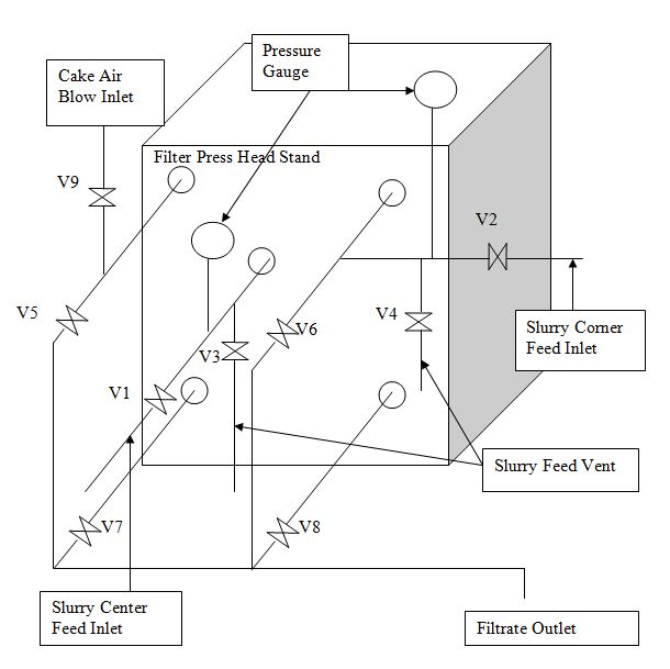
Figure 6. Membrane Piping for HPL300 Filter Press
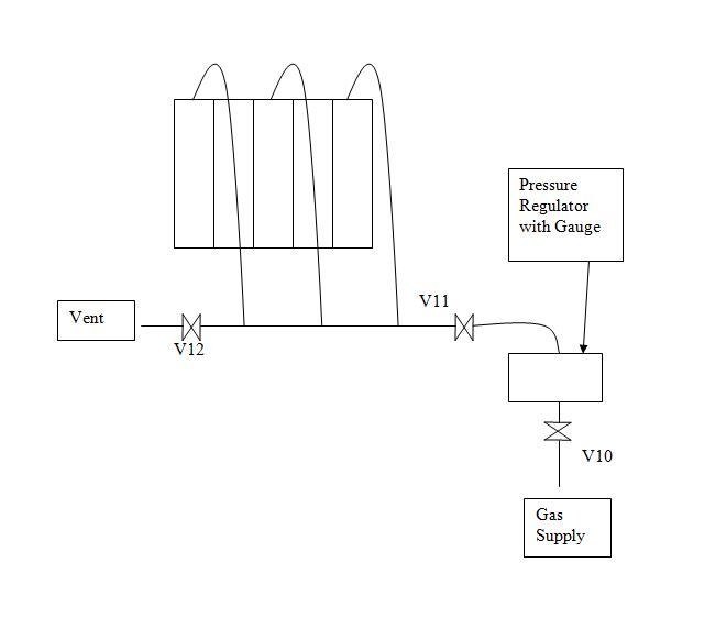
Quick Disconnects Not Shown
Table 8. Plate Data for HPL300 Filter Press